 |
The model described in previous section has been employed to calculate the response of the four CsI slabs constituting the GRBM. A monochromatic point source is located at 5 meters from the center of the detector. The program is run to produce a statistically significant number of pulses in the four shields (typical error of 3-5 % for a well exposed shield). The source is then moved to the adjacent position, 10 degrees farther along the circumference, and another run is performed. With 36 of these positions the whole circumference is completed and the diagram with the angular response can be drawn. The results thus obtained are compared with the ESTEC on-ground calibration.
The simulation in the equatorial plane has been performed with sources of different energies, and the same job will be performed at other angles of latitude (15, 30, 45, 60, -15, -30) to benchmark the measurements made during the experimental on-ground calibration.
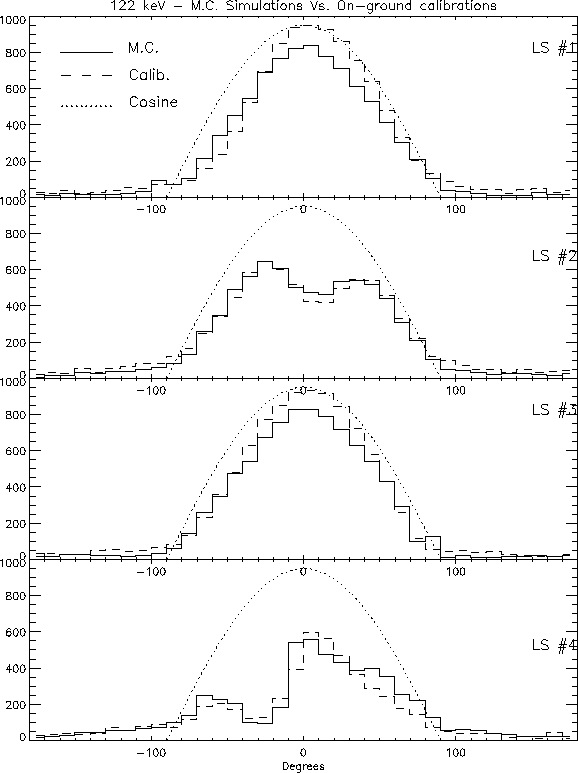
Figure 3.23 reports the response functions of the four Lateral Shields (LS) to a monochromatic 57Co source located in 36 positions, along the equatorial circumference of radius 5 m, 10 degrees one from the other. The dashed lines represent the experimental response function, the solid lines the response simulated by the Monte Carlo, and the dotted lines the simple cosine response that one would expect if the effects were purely geometrical. The experimental response, obtained during the slow rotation of the satellite was averaged along the ten degrees path and rebinned to match the simulated point source. LS1 is the shield behind the concentrators of the two MECS, LS2 behind the HPGSPC, LS3 behind the MECS and LECS concentrators, and LS4 behind the WFCs. At present we have not yet attempted to simulate the absolute response of the shields to the source, due to some refinements in the model still in progress. Thus, to compare the results, the experimental and the simulated responses are normalized in the shield 2 with the assumption that the total area under the two curves is the same. In first approximation the agreement between the two curves is remarkable. The Monte Carlo simulation confirms that the fields of view of LS1 and LS3 (those behind the carbon-fiber tubes of the X-ray telescopes) are practically free of obstacles and show a response close to the geometrical one. The agreement between the simulated and the experimental response is very close also in the LS2 and LS4, where the main features of the curves are reproduced.
A closer view shows, however, that the small differences are significant. For instance, the rise and fall of the source in LS4 is broader in the simulation than in reality. Moreover, if the normalization in LS2 is correct, the efficiency of the 'good' shields (LS1 and LS3) is underestimated by the Monte Carlo. The discrepancies between the simulated and experimental responses are more visible at the lower energy of 241Am. If also in this case the overall normalization on the shield LS2 is correct, too much material is present in one of the two concentrators in front of the shield LS1, which are simulated equal. The worst situation is in the response of the LS4, where the presence of some material must have been underestimated. Other energies and other latitudes are being investigated at the moment, giving results substantially in agreement between the simulation and the experiment, but still with lesser discrepancies that suggest a further work of refinement along particular lines of sight.