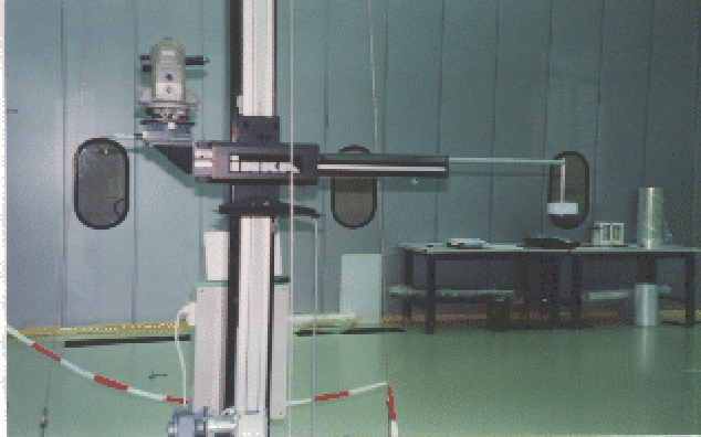
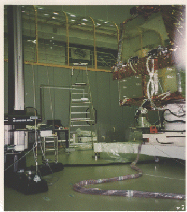
SAX was set onto a rotary table, in the Z axis vertical direction, and the
tooling bar was located at about 570 cm from the PDS center (Fig. 2.3). By means of a
coordinated shift of the movable horizontal arm of the tooling bar and a
movement of the source support onto the extended arm it was possible to reach
positions lying onto a virtual spherical surface centered on PDS and having 500
cm radius. During the calibrations, the energy thresholds were fixed at the
following levels: LLT at minimum value (nominal 20 keV), ULT at maximum value
(nominal 700 keV) and ACT at minimum value (nominal 100 keV). A first set of
measurements was carried out with the SAX satellite that rotated around Z axis
on the rotary table at a fixed angular speed of ![]() 9 arcmin/s. With this
angular speed, a complete rotation of SAX lasted 2304 s, which means 18 time
periods of 128 s (accumulation time of GRBM spectra). The sources were
positioned at various elevation angles, ranging from
9 arcmin/s. With this
angular speed, a complete rotation of SAX lasted 2304 s, which means 18 time
periods of 128 s (accumulation time of GRBM spectra). The sources were
positioned at various elevation angles, ranging from ![]() to
to ![]() with respect to the horizontal (X,Y) plane. The
angular response of each GRBM shield was thus measured from GRBM and AC ratemeters.
with respect to the horizontal (X,Y) plane. The
angular response of each GRBM shield was thus measured from GRBM and AC ratemeters.
| Energy | -45 | -30 | -15 | +15 | +30 | +45 | +60 | |
| 241Am | Y | Y | Y | Y | Y | Y | Y | Y |
| 57Co | Y | Y | Y | |||||
| 139Ce | Y | Y | Y | Y | Y | |||
| 203Hg, | Y | |||||||
| 113Sn | Y | Y | Y | Y | Y | |||
| 85Sr | Y | |||||||
| 137Cs | Y |
Also, average energy response over 128 s, corresponding to a rotation of 20 degrees, was determined.
Hereafter we will express source direction with respect to each LS in the altazimuthal coordinates ![]() , i.e. the angle between source direction and the satellite XY plane, and
, i.e. the angle between source direction and the satellite XY plane, and ![]() , i.e. the angle between the projection of source direction onto the XY plane and the detector axis.
, i.e. the angle between the projection of source direction onto the XY plane and the detector axis.
In Tab. 2.2
we report the energy and ![]() values 'covered' by these kind of measurements.
The number of runs was limited by time constraints. Several background measurements ware made, with no source in the tooling bar arm end without altering
the calibration set-up.
values 'covered' by these kind of measurements.
The number of runs was limited by time constraints. Several background measurements ware made, with no source in the tooling bar arm end without altering
the calibration set-up.
A second set of measurements was carried out with the SAX satellite fixed in some particular positions, in order to better understand some shielding effects. This was done, in particular, for LS2 and LS4, whose angular responses were expected to be more complex because of the presence in front of them of the HPGSPC and WFCs respectively.
During these calibrations, the PDS was operated in standard mode and all the other scientific instruments were off.